Wedge Barriers Can Be Fun For Everyone
Some Of Wedge Barriers
g., spring assistance 65 )might be taken care of to the end of the springtime rod 58 to enable compression of the springtimes 60. As the springs 60 are compressed in between the spring sustains 62, the springtime assembly 54 generates a force acting on the camera combined to the springtime pole 58 in an instructions 66. For instance, the remaining force related to
the cam to release the wedge plate 16 might be supplied by an electromechanical actuator 84 or other actuator. The spring setting up 54 and the actuator 84(e. g., electromechanical actuator)might operate together to translate the web cam and raise the wedge plate 16.
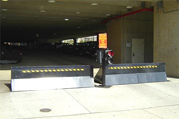
As discussed over, the spring setting up 54 exerts a constant pressure on the cam, while the electromechanical actuator may be regulated to put in a variable pressure on the web cam, consequently allowing the lifting and decreasing( i. e., deploying and withdrawing )of the wedge plate 16. In certain embodiments, the continuous pressure used by the springtime assembly 54 might be flexible. g., electromechanical actuator) is impaired. As will be valued, the spring setting up 54 might be covered and secured from debris or other components by a cover plate(e. g., cover plate 68 revealed in FIG. 4) that might be substantially flush with the raised surface area 38 of the foundation 14. As stated above, in the released placement, the wedge plate 16 offers to obstruct accessibility or traveling past the obstacle 10. The barrier 10(e. g., the wedge plate 16 )might block pedestrians or cars from accessing a residential property or pathway. As discussed above, the obstacle 10 is connected to the support 30 safeguarded within the structure 14,
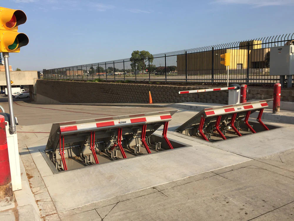
front braces 71. Consequently, the linkage settings up 72 might pivot and turn to enable the collapse and expansion of the linkage settings up 72 throughout retraction you can try here and release of the bather 10. The affiliation settings up 72 reason movement these details of the wedge plate 16 to be limited. For instance, if a lorry is taking a trip towards the released wedge plate 16(e. As an example, in one condition, the safety legs 86 may be extended duringupkeep of the obstacle 10. When the safety and security legs 86 are released, the safety and security legs 86 sustain the weight of the wedge plate 16 versus the surface area 12. Therefore, the training mechanism 50 might be deactivated, serviced, gotten rid of, changed, and so forth. FIG. 5 is partial viewpoint view of a personification of the surface-mounted wedge-style obstacle 10, highlighting the web cam 80 and the web cam surface areas 82 of the training mechanism 50. Especially, two web cam surface areas 82, which are described as reduced web cam surface areas 83, are placed listed below the web cam 80. The lower cam surfaces 83 might be dealt with to the surface area 12 (e. For instance, the reduced webcam surfaces 83 and the mounting plate 85 may form a single item that is secured to the anchor 30 by screws or various other mechanical fasteners. In addition, two cam surface areas 82, which are described as upper camera surfaces 87, are positioned over the camera 80 and coupled to (e. In various other personifications, stepping in layers or plates might be placed between the surface area 12 and the reduced camera surfaces 83 and/or the wedge plate 16 and the top camera surface areas 87 As discussed over, the camera
80 converts along the web cam surfaces 82 when the wedge plate 16 is lifted from the pulled back placement to the deployed placement. Additionally, as pointed out above, the spring setting up 54 (see FIG. 3 )may offer a pressure acting on the webcam 80 in the direction 102 using spring pole 58, which might lower the pressure the electromechanical actuator 84 reference is needed to put on the webcam 80 in order to actuate and raise the wedge plate 16. 1 )to the deployed setting(see FIG. 4). As revealed, the cam 80 includes track wheels 104(e. g., rollers), which get in touch with and convert along the cam surfaces 82 throughout operation.